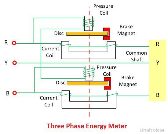
Three phase energy meter connection wiring diagram meter board.
Calibration of single phase energy meter circuit diagram.
In a typical residential single phase meter form 2s type the upper two lugs are connected to utility source and lower lugs are connected to the house branch circuit panel.
The stpm10 consists of two main sections.
Presented here is a simple energy meter using analog device s ade7757 chip for single phase 2 wire phase and neutral systems used in households.
The magnetic field produced by series magnetic in phase with the line current and magnetic field produced by shunt magnet is in quadrature with the applied voltage thus a phase difference exists between the fluxes produce by the two.
The device can be implemented for peripheral measurement in a microcontroller based single phase or poly phase energy meter.
220v 10 50 60hz li polymer battery size mm.
6 tft 640 480 power supply.
Includes single phase 2 phase supply 3 phase supply multiple installations distributed generation alternative energy and typical equipment dimensions.
When the energy meter is connected in circuit the current coil carries the load current and pressure coil carries the current proportional to the supply voltage.
The meter is less expensive and accurate.
The analog part is composed of preamplifier and first order sigma delta a d converter blocks a band gap voltage reference and low drop voltage regulator.
1 electrical parameters accuracy class.
The connection and circuit diagram of single phase 3 phase 4 wire kwh meter digital or analog energy meter from the supply to the main distribution board in the above graphics and diagrams p in incoming phase or live from the source supply voltage.
The energy is the total power consumed and utilised by the load at a particular interval of time it is used in domestic and industrial ac circuit for measuring the power consumption.
Single phase energy meter connection youtube based training bd.
But these are now being gradually replaced by electronic digital energy meters.
Meter wiring diagrams for low voltage meter stations for in whangarei and kaipara.
The meter which is used for measuring the energy utilises by the electric load is known as the energy meter.
Apply a load of 2 amps by switching on the load.
Apply 220v a c to the pressure coil circuit by means of phase shifting transformer.
Engineering circuit analysis duration.
Procedure for calibration and testing of single phase energy meter give the connections as per the circuit diagram above.

